


Cat5 Wiring: A Step-by-Step Tutorial for Beginners
As one of the most common Ethernet cable types used in networking, it's important for both IT professionals and home networkers to understand Cat5 wiring fundamentals. Being able to properly wire and crimp Cat5 and Cat5e cables enables you to create custom patch cables and connections for modern networking applications.
Before running cables for your wired infrastructure, it's essential to learn the critical Cat5 guidelines around twisted pair arrangements, cabling standards, and termination techniques. This article serves as an in-depth, beginner-friendly tutorial on everything related to Cat5 wiring.
How does Cat5 Wiring Work?
Cat5 wiring works by using four twisted pairs of copper wires to transmit data signals between devices through Ethernet connections. The twisting reduces interference, allowing stable data transfer up to 100 Mbps.
What Is Cat5 Wiring?
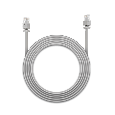
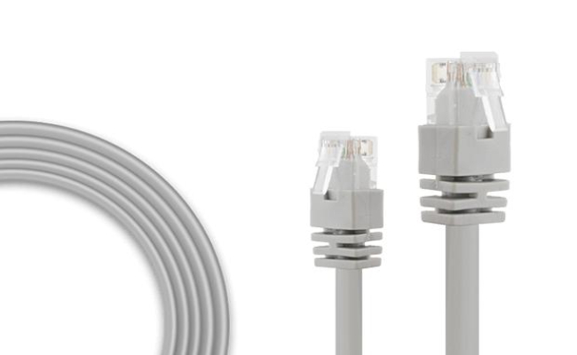
A cat5 wiring cable is an Ethernet cable used in computer networking and telecommunications wiring. The cables consist of four twisted pairs of copper wire terminated by RJ45 connectors.
How Cat5 Wiring Transmits Data
- Data travels as electrical signals through copper wires
- The four twisted pairs help reduce signal interference (crosstalk)
- Each pair carries signals that enable communication between devices
- RJ45 connectors link the cable to network devices like routers and switches
Key Features of Cat5 Wiring
- Supports fast Ethernet network speeds up to 100 Mbps
- Made up of four twisted pairs of copper wires
- Used with RJ45 connectors and Ethernet ports
- Often used for connecting network devices and patching network connections
- Provides PoE to power devices over the Ethernet cable
What Is Cat5 Wiring Used For?
- LAN (Local Area Network) connections
- Connecting routers, switches, and computers
- Powering devices like IP cameras and Wi-Fi access points via PoE
Cat5 Wiring + PoE (Power over Ethernet)
Cat5 cables can also deliver power along with data using PoE. This allows a single cable to:
- Transmit data
- Supply power to compatible devices
Common PoE devices include:
- IP cameras
- Wi-Fi access points
Cat5 wiring is an Ethernet networking cable capable of 100 Mbps network speeds, made of four twisted pairs of copper wires, and used with RJ45 connectors. It is a core component of wired networks and PoE connections.
What Are Two Standards of Cat5 Wiring?
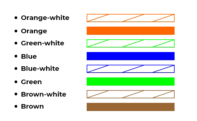
Cat5 cable contains four twisted pairs of copper wire. These wires are color-coded and must follow a specific wiring scheme to work properly.
There are two main wiring standards used for Cat5 wiring:
- T568A
- T568B
The wiring scheme determines the order and color orientation of the wires in each RJ45 connector at both ends of the Cat5 cable. If the cables at each end don't follow the same wiring standard, the connection may not work at all.
T-568A Standard
The T-568A standard specifies a specific cat5 wiring color code order for proper connectivity.
Wiring Diagram
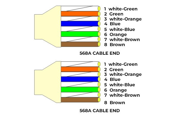
Color Code Order
- White/Green
- Green
- White/Orange
- Blue
- White/Blue
- Orange
- White/Brown
- Brown
T-568B Standard
The T-568B standard provides an alternate wire color order commonly used in many network installations.
Color Code Order
- White/Orange
- Orange
- White/Green
- Blue
- White/Blue
- Green
- White/Brown
- Brown
Key Difference Between T568A and T568B
- The only difference is the orange and green wire pairs are swapped between the two standards.
Cat5 wiring uses two standards—T568A and T568B—to define wire color order in RJ45 connectors. Both work the same, but consistency on both ends of the cable is essential for proper network performance.
Cat5 Wiring Diagrams: Straight-through vs. Crossover
Cat5 wiring diagrams define how the wire terminals are configured at each RJ45 connector on both ends of a cable. There are two main types of Cat5 wiring diagrams:
- Straight-through
- Crossover
The choice of diagram determines how wires are connected and what devices can communicate.
1. Straight-through Cat5 Wiring Diagram
- Uses the same wiring specification at both connectors
- Pins 1–8 at one connector connect directly to the identical pins 1–8 on the other end
- Wire color order is identical at both ends
Visual Example
How It Works
- Connects all wire pairs straight through
- Transmit (Tx) and receive (Rx) pairs match at both ends
Use Cases
- Connecting computers to network switches or routers
- Ethernet wall port connections
- Standard LAN connectivity
2. Crossover Cat5 Wiring Diagram
- Transmit (Tx) wires on one end are swapped with receive (Rx) wires on the other end
- Wire pinouts 1–3 and 2–6 are flipped between the two connectors
Visual Example
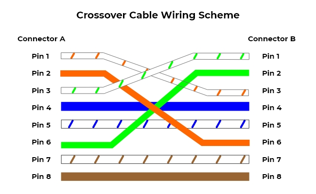
How It Works
- Transmit pairs at one end connect to receive pairs at the other end
- Enables direct communication between like devices without a central network device
Use Cases
- Connecting two computers directly
- Linking two network switches without a hub or router
Key Takeaways
- Straight-through cables connect different devices (computer ↔ switch/router)
- Crossover cables connect like devices (computer ↔ computer, switch ↔ switch)
- Choosing the correct Cat5 wiring diagram is essential for proper network connectivity
How to Read Cat5 Wiring Pinouts?
Correct orientation is key when working with Cat5 wiring. Check the following steps.
- Understand wiring standards. Cat5 cables follow two main wiring standards: T568A and T568B. Each defines the order of the 8 colored wires inside the cable.
- Identify the pin numbers and following the right direction: Pins are numbered 1 to 8 on the RJ45 connector from left to right, with the clip facing down.
- Match wire colors to pins. Follow the chosen standard to map each wire color to its corresponding pin.
How to Wire a Cat5 Cable: Step-by-Step Guide
Wiring your own Cat5 Ethernet cables is a fairly straightforward process with the right tools. Here is a step-by-step guide:
Step 1: Gather the Required Components
First, gather all the materials you'll need:
- Cat5, Cat5e or Cat6 twisted pair cable
- Cat5 plug wiring
- RJ45 connectors
- RJ45 crimping tool
- Wire cutter/stripper tool
Make sure to get enough Ethernet cat5 rj45 wiring cables to run between your devices without pulling too tight.
Step 2: Cut and Strip the Cable Ends
Use your wire cutters to cut both ends of the Cat5 cable to the desired length. Leave a little extra length to work with.
Then, use the wire strippers to remove 1 to 1.5 inches of the outer sheath jacket from both ends, exposing the 4 internal wire pairs.
Step 3: Untwist and Organize Wire Pairs
Carefully untwist each wire pair at the end and neatly align them according to the wiring scheme you’re using (T568A or T568B).
The wires must extend a uniform length from the jacket to insert into the RJ45 plug.
Step 4: Insert the Wires into the RJ45 Plug
Hold the RJ45 connector clip side down and insert the aligned wires firmly into the grooves following your wiring diagram (A or B).
Double-check that each cat5 end wiring is fully inserted into the front of the connector and matches the wiring scheme.
Step 5: Crimp the RJ45 Connector
Place the loaded RJ45 connector into the crimping tool. Make sure it’s fully seated flush in the crimper.
Go ahead and crimp it down firmly. This may take considerable force to punch down and make solid contact.
Step 6: Repeat Steps on the Other End
Repeat steps 2-5 for the other end of the Cat5 cable. It's crucial both ends follow the same wiring scheme for straight-through connections.
And you’re done! Test the crimps are solid and the connection works before permanently installing them in your network.
Cat5 Wiring for PoE IP Cameras: A Real-World Example
Cat5 cables are commonly used to connect PoE (Power over Ethernet) IP cameras to a network. These cables carry both data and power over a single line, simplifying installation and reducing the need for extra power adapters.
Using Cat5 wiring correctly ensures your cameras receive stable data transmission and sufficient power for reliable operation.
How Cat5 PoE Wiring Works for PoE Cameras
- Data Transmission: Ethernet signals travel over the twisted copper pairs.
- Power Delivery: PoE sends DC power along specific wire pairs in the Cat5 cable.
- RJ45 Connection: Each end of the cable uses RJ45 connectors, following either a straight-through wiring standard (T568A or T568B).
Real-World Setup Example
Suppose you want to install a PoE IP camera in your home or office:
- Choose the Cable: Use a Cat5 or Cat5e cable rated for your camera distance.
- Wire the Cable: Follow a straight-through Cat5 wiring standard at both ends for proper PoE functionality.
- Connect Devices:
- One end connects to the IP camera
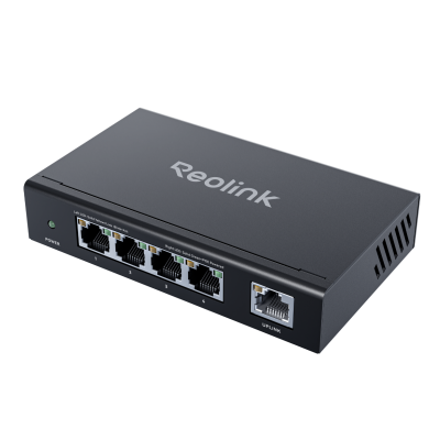
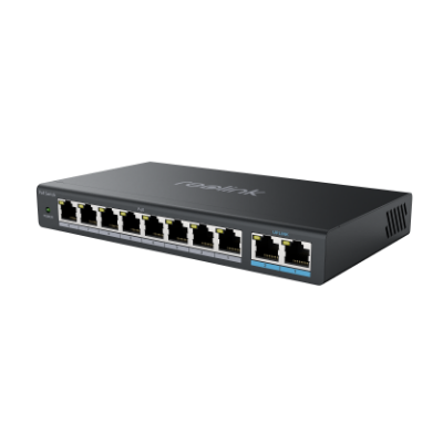
- The other end connects to a PoE-enabled switch or injector
- Test the Connection: Make sure the camera powers on and transmits video to your network
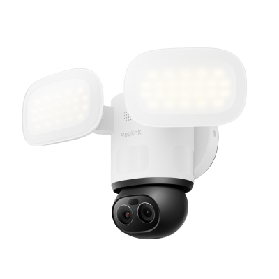
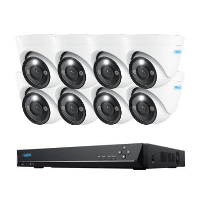
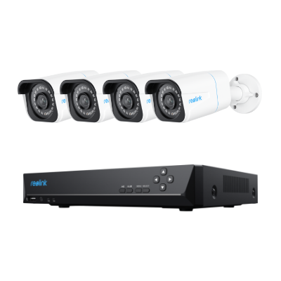
Reolink's Top Picks for PoE Wiring
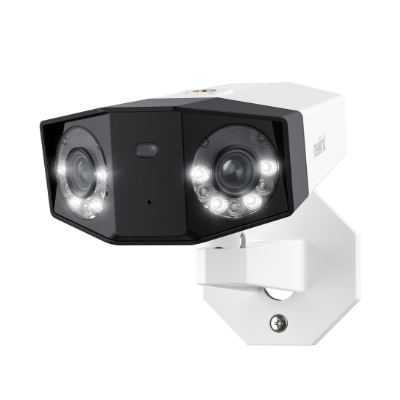
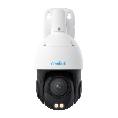
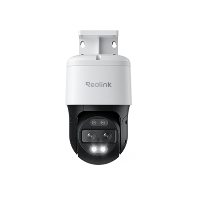
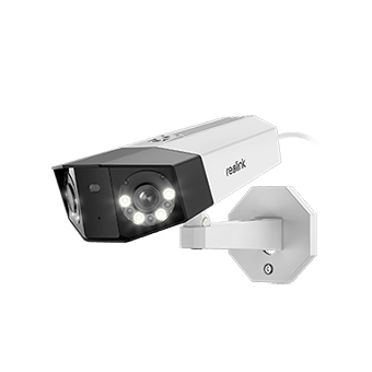
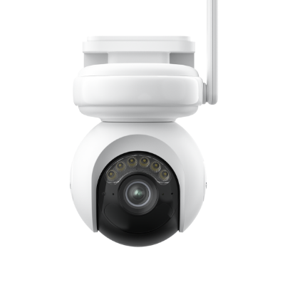
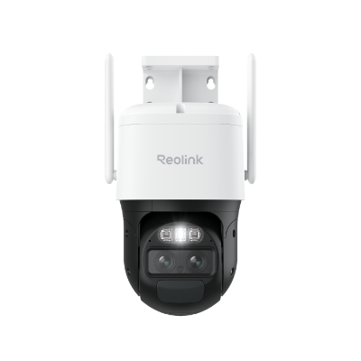
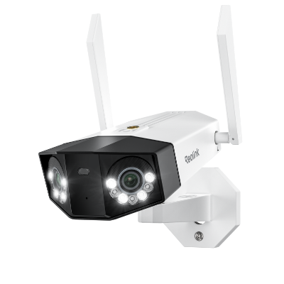
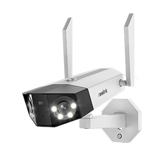
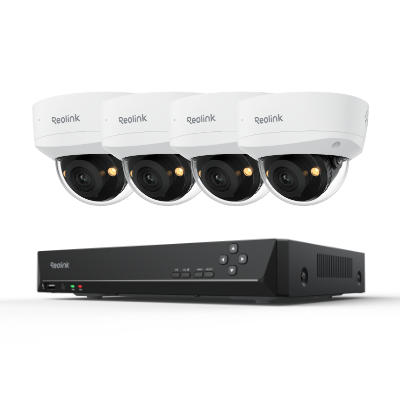
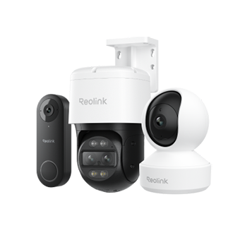
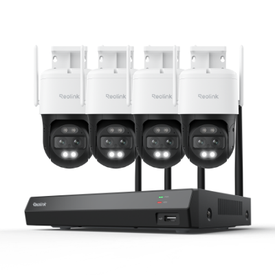
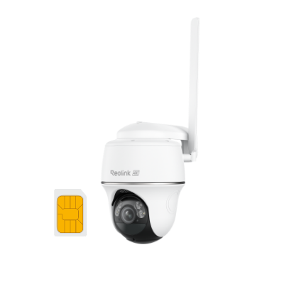
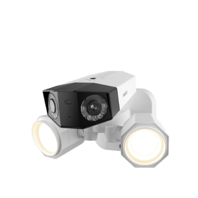
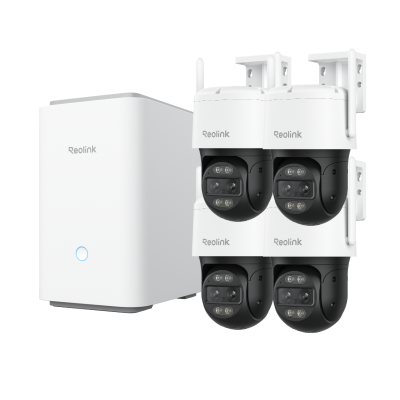
Reolink Duo 3V PoE – This dual‑lens PoE security camera delivers 16 MP UHD resolution with a full 180° panoramic view, so one unit can cover wide areas without blind spots. It uses advanced motion track and smart detection to alert you to people, vehicles, or animals in real time and streams sharp video day and night with spotlight night vision. With PoE connectivity and IP67 weatherproofing, setup is simple and reliable for outdoor security.
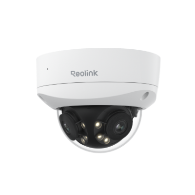
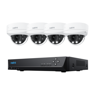
16MP Dual-Lens IK10 Vandal-Proof PoE Camera
16MP Ultra HD, 180° Panorama, Motion Track, IK10 Vandal-Proof, color night vision.
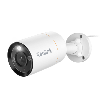
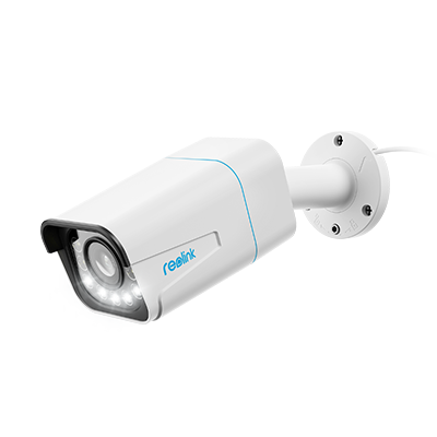
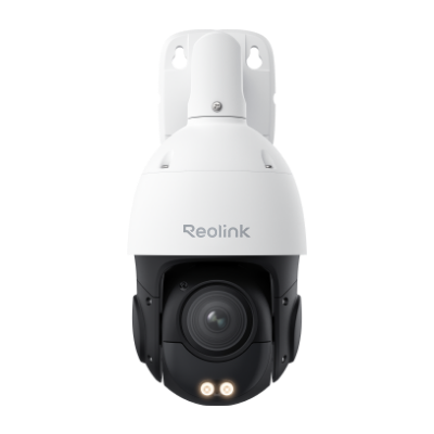
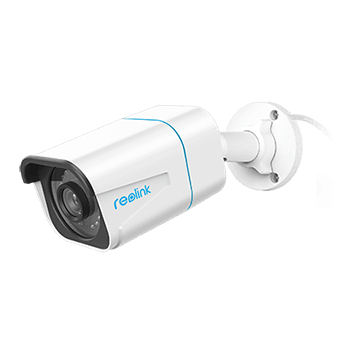
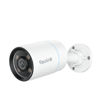
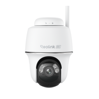
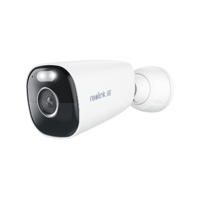
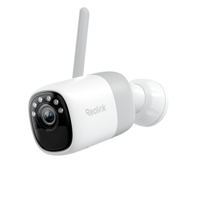
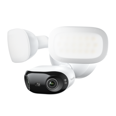
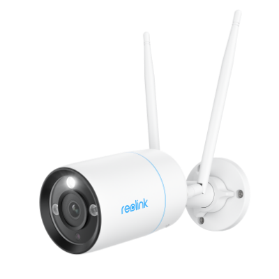
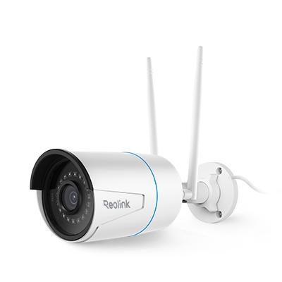
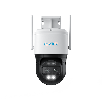
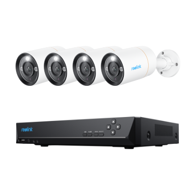
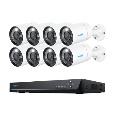
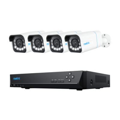
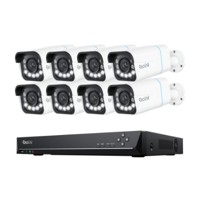
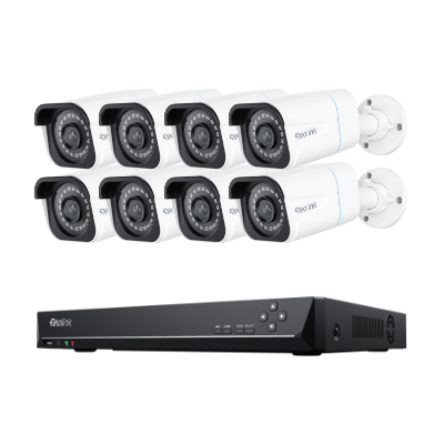
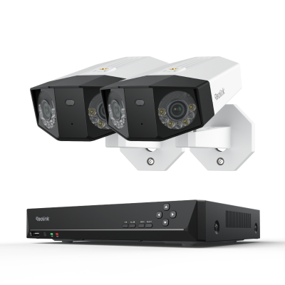
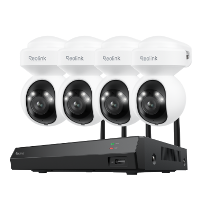
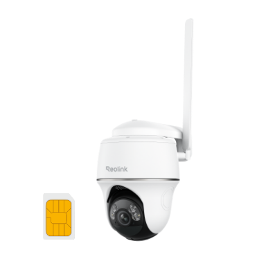
Reolink RLC‑811A – This 4K Ultra HD PoE bullet camera gives you detailed surveillance with color night vision, spotlights, and a motorized varifocal lens with 5× optical zoom for flexible coverage. Its smart detection can distinguish people, vehicles, and pets to reduce false alerts, while two‑way audio lets you listen and talk through the camera. Easy PoE installation and customizable recording options make it a strong choice for home or business security setups
4K Smart PoE Camera with 5 Spotlights
4K 8MP Ultra HD Day & Night, Person/Vehicle Alerts, 5X Optical Zoom, Two-Way Audio, Built-in Siren, Color Night Vision, Live View Anywhere.
FAQs
What is the wire order for Cat5?
Cat5 cables contain 8 wires in 4 twisted pairs. The order depends on the wiring standard you use:
T568A Standard (pin 1 → pin 8):
- White/Green
- Green
- White/Orange
- Blue
- White/Blue
- Orange
- White/Brown
- Brown
T568B Standard (pin 1 → pin 8):
- White/Orange
- Orange
- White/Green
- Blue
- White/Blue
- Green
- White/Brown
- Brown
Both ends of a cable must follow the same standard for a straight-through connection, while a crossover cable swaps the transmit and receive pairs.
Which is better, T568A or T568B?
Both standards perform the same; there’s no speed or reliability difference. T568A is common in residential networks and government installations. T568B is more widely used in commercial environments.
What does the color code mean on Cat5 wires?
The color code on Cat5 wires identifies the four twisted pairs used for data transmission and, in some cases, Power over Ethernet (PoE). Each pair—White/Green + Green, White/Orange + Orange, White/Blue + Blue, and White/Brown + Brown—carries specific transmit or receive signals, and the twisting reduces interference between pairs.
Conclusion
Wiring Ethernet cables properly is essential whether installing home networks or large-scale cabling infrastructure. Understanding Cat5 specifications, wiring diagrams, crimping procedures, and related components gives you the knowledge to work with these ubiquitous cables.
Applying the step-by-step wiring tutorial allows even network novices to customize Cat5 patch cables. When planning out your connectivity needs, be sure to use the appropriate grade of cable and connections to achieve maximum speed and reliability. Have you ever tried to run Cat5 wiring by yourself? Share your experience with us and let us discuss together!
- How to Install Security Camera Wiring For Both Outdoors and Indoors : Step-by-Step Guide & Videos
- How Much Do You Know about Cat 5/Cat 6 IP/CCTV Security Cameras/Systems
- CCTV Camera Connection: Start-to-Finish Guide & Setup Videos
- How to Connect a DVR/NVR to the Internet & Set Them Up for Remote Viewing
Search
Subscribe for the Latest Updates
Security insights & offers right into your inbox