How to Terminate Ethernet Cable: DIY Made Simple
Ethernet cables are integral to a home network or corporate infrastructure. Mastering the DIY steps of terminating Ethernet cables is fundamental for optimal connectivity. This article will explore the basic steps on how to terminate Ethernet cables. You'll discover helpful insights here, whether you're terminating a Cat5e or a Cat6 cable.
- Understanding Ethernet Cables
- Essential Tools and Preparation for Ethernet Cable Termination
- How to Terminate Ethernet Cable: Step-by-Step Guide
- How to Maintain Ethernet Cable for Optimal Performance?
- What Are Some Common Mistakes to Avoid When Terminating Ethernet Cables?
- Step-by-Step PoE Camera Termination Guide
- FAQs
- Conclusion
Understanding Ethernet Cables
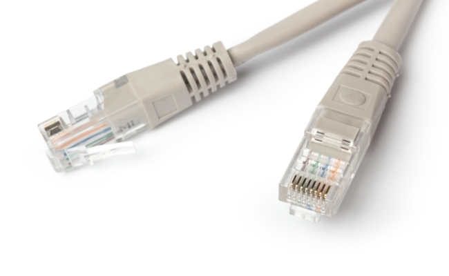
As a type of wired network cable, Ethernet cables can connect devices in a local area network (LAN) for data transmission.
- Cat5e: Cat5e cables support speeds up to 1 Gbps (Gigabit per second) and operate at a frequency of 100 MHz. This type is widely used in most home and small business networks.
- Cat6: Cat6 cables offer higher performance compared to Cat5e. They can support speeds up to 10 Gbps over shorter distances (up to 55 meters) and operate at frequencies up to 250 MHz. These cables are suitable for those demanding higher data transfer rates.
- Cat6a: These cables are an enhanced version of Cat6. They support even higher speeds (up to 10 Gbps) over longer distances (up to 100 meters) at frequencies up to 500 MHz. Cat6a cables are more resistant to crosstalk and interference.
Note: This guide will primarily cover terminating Cat5e and Cat6 Ethernet cables since they're commonly utilized in networks.
Essential Tools and Preparation for Ethernet Cable Termination
1. Cable Cutter and Jacket Stripper
A clean cut is the foundation of a reliable Ethernet connection. A proper cable cutter ensures the cable is trimmed without crushing the internal wiring, while a jacket stripper safely removes the outer PVC sheath.
- Prevents damage to twisted pairs
- Maintains cable integrity for stable signal transmission
- Many crimping tools include built-in cutters and strippers
2. RJ45 Connectors (8P8C Modular Plugs)
RJ45 connectors are the termination point of your Ethernet cable and are essential for creating a functional network connection.
- Standard 8P8C Ethernet plug design
- Must match cable type (Cat5e or Cat6 compatible)
- Pass-through RJ45 connectors make wiring easier and more accurate
Tip: Pass-through connectors allow wires to extend beyond the plug for easier alignment before crimping.
3. RJ45 Crimping Tool
The crimping tool is the core device used to secure the RJ45 connector to the cable.
- Presses gold contacts into copper wires
- Locks connector onto the cable jacket for strain relief
- Essential for both standard and pass-through RJ45 plugs
For pass-through connectors, choose a crimper with a built-in trimming blade to cut excess wire cleanly.
4. Wire Straightener and Precision Snips
After stripping the cable, the twisted wire pairs must be untangled, aligned, and trimmed to match the correct wiring standard (T568A or T568B).
- Ensures proper pin alignment
- Reduces signal interference and errors
- Flush snips help create an even wire length before insertion
5. Cable Boots (Strain Relief Covers)
Cable boots are often overlooked but provide important protection for long-term durability.
- Prevent RJ45 latch breakage
- Reduce strain on the connector
- Improve overall cable lifespan
6. Continuity Cable Tester
A cable tester is essential for verifying a successful termination before deployment.
- Checks all 8 conductors for continuity
- Detects wiring errors such as shorts or open circuits
- Confirms correct pinout (T568A or T568B)
A simple LED sequence test ensures your Ethernet cable is fully functional.
7. Optional Tools for Structured Cabling
For more advanced installations, especially in homes or offices:
- Punch Down Tool – Used for keystone jacks and patch panels
- Keystone Jacks – Wall outlet termination points for Ethernet cables
- Patch Panels – Centralized network cable management systems
- Cable Labels – Helps identify and organize multiple runs
- Velcro Cable Ties – Keeps installations neat and organized
How to Terminate Ethernet Cable: Step-by-Step Guide
Step 1. Measure and Cut the Cable
Use your cable cutter to snip the Ethernet cable to your exact desired length. Make a clean, 90-degree square cut across the cable. If you are new to termination, add an extra 2 to 3 inches of length to give yourself a buffer case you need to re-strip or correct a mistake.
Step 2. Strip the Outer Insulation Jacket
Insert the cable end into your jacket stripper. Carefully score and spin the tool to strip off roughly 1.5 inches (4 cm) of the outer PVC jacket. Pull the cut insulation piece off to expose the internal twisted wire pairs.
Crucial check: Inspect the inner wires closely—if you see any nicks or cuts exposing bare copper, clip the end off completely and repeat the step with less pressure.
Step 3. Remove the Spline and Ripcord (Cat6 Only)
If you are terminating a Cat6 cable, you will see a central plastic cross-spline separating the wire pairs. Pull the four wire pairs back and use your flush snips to cut this plastic spine as deep and flush with the edge of the outer jacket as possible. Snip off the thin thread ripcord at this stage as well.
Step 4. Untwist, Straighten, and Arrange Wires
Untwist the core wire pairs all the way down to the edge of the jacket. Using your thumb and index finger, massage and straighten each individual conductor so they sit perfectly flat side-by-side. Arrange the eight wires horizontally matching your chosen pinout standard. T568B is the universal standard for modern commercial networks.
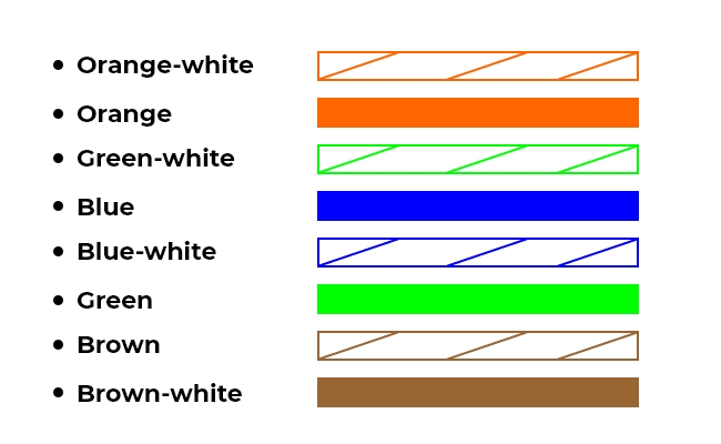
Note: The color order of T568A is White/Green; Green; White/Orange; Blue; White/Blue; Orange; White/Brown; Brown.
Step 5.Trim Wires to Uniform Length
Gather your flattened, color-sorted wire array tightly together between your fingers. Using sharp flush snips, make a clean cut perfectly straight across the wires. If you are using standard closed-ended RJ45 plugs, trim the exposed wires so they extend exactly 0.5 inches (1.3 cm) past the jacket line. If you are using pass-through plugs, leave them long.
Step 6. Insert Wires into the RJ45 Plug
Hold the RJ45 modular plug so that the plastic locking clip is facing DOWN and the gold-plated pins are facing UP towards you. Slide your wire array smoothly into the back of the plug. Keep pushing forward until the individual wires slide into their respective guide tracks and firmly press flat against the very front edge of the clear plug shell.
Step 7. Verify Jacket Seating and Alignment
Before crimping, check two critical zones. First, look through the top of the plug to confirm that your color sequence did not cross over or shift during insertion. Second, ensure that about 1/4 inch of the thick outer PVC jacket is sitting inside the back of the plug, resting past the internal plastic wedge locking tab. If the jacket doesn't reach the tab, your wires will quickly pull loose under strain.
Step 8. Crimp and Seal the Connection
Insert the loaded plug fully into the 8P/RJ45 cavity of your ratcheting crimping tool. Firmly squeeze the handles completely through their cycle until the tool releases. This mechanical action drives the gold pins down into the copper cores and compresses the internal plastic wedge onto the cable jacket. If you are using a pass-through tool, it will automatically slice off the excess wire tips dangling out the front.
Step 9. Repeat and Validate Connection
Repeat Steps 2 through 8 on the opposite end of your cable length, ensuring you build an identical T568B to T568B link. Once both sides are complete, plug the ends into your continuity cable tester and turn it on. The LEDs on the master and remote units should light up sequentially from 1 through 8. If any lights fail to illuminate or skip order, cut that end off and re-terminate.
How to Maintain Ethernet Cable for Optimal Performance?
After terminating Ethernet cables, you need to maintain these cables properly for optimal performance.
- Secure Cable Routes: Ethernet cables should not be sharply bent or twisted excessively during installation. You must also secure cables from hazards like heat sources, sharp edges, or areas with high foot traffic.
- Maintain Proper Bend Radius: Follow recommended bend radius guidelines to prevent stress on the cable. Cat6 cables, for instance, require a larger bend radius than Cat5e.
- Organize Cables: Use cable management tools like clips, ties, or raceways to keep cables organized and prevent tangling or entanglement.
- Avoid Possible Interference: Keep Ethernet cables away from sources of electromagnetic interference like power cables, fluorescent lights, or machinery.
- Check Cables and Connectors Regularly: Use cable testers periodically to check the continuity and quality of connections. Inspect connectors regularly for damage, corrosion, or loosening and replace damaged connectors promptly.
What Are Some Common Mistakes to Avoid When Terminating Ethernet Cables?
When DIY terminating Cat5e or Cat6 lines, look out for these common errors:
1. Excessive Untwisting of the Wire Pairs
The internal copper wires are twisted precisely to cancel out electromagnetic interference and crosstalk from adjacent wires.
- The Mistake: Installers often untwist the pairs too far back (more than 0.5 inches from the crimp point) to make sorting easier.
This severely degrades signal performance. It can cause a Cat6 cable meant for 1 Gbps or 10 Gbps speeds to bottleneck down to 100 Mbps or fail verification entirely. Keep the twists intact right up to the entry point of the plug.
2. Not Seating the Cable Jacket Under the Locking Wedge
The clear plastic body of an RJ45 plug features a small internal indentation or plastic wedge toward the rear.
- The Mistake: Trimming the individual wires too long, leaving the thick outer PVC insulation jacket outside the plug housing.
The crimper's strain-relief clamp will push down onto bare, fragile wires instead of the tough jacket. The moment the cable is pulled or bent, the internal wires will slip backward out of their pins, ruining the connection.
3. Nicking the Internal Conductor Insulation
When scoring the thick outer PVC jacket with a spinning stripping tool, finding the right amount of pressure is tricky.
- The Mistake: Pressing too hard with the stripping blade, which slices through the outer jacket and nicks the thin insulation of the inner copper wires.
Exposed copper wires can touch each other inside the cable, creating a short circuit. Alternatively, the nicked copper core becomes physically weak and will snap cleanly in two inside the jacket later on.
4. Overlooking the Pinout Orientation (The Upside-Down Flip)
It is easy to get the color code sequence exactly right on your flat workspace but completely reverse it during insertion.
- The Mistake: Arranging the color sequence correctly from left to right, but sliding it into the RJ45 plug with the clip side facing up instead of down.
This creates an inverted mirror image of the pin layout. Pin 1 becomes Pin 8, completely reversing the transmission lines and causing an instantly non-functional cable.
5. Mixing T568A and T568B Standards on a Single Link
Both T568A and T568B pin layouts work perfectly fine, but they route traffic across different color positions.
- The Mistake: Terminating one side of your custom cable using the T568B layout and accidentally using T568A on the opposing side.
You have inadvertently created a crossover cable. While some modern networking switches feature auto-sensing ports (MDI-X) that can auto-correct this, it frequently leads to performance confusion, device incompatibility, and intermittent connectivity drops on standard wall plates.
Step-by-Step PoE Camera Termination Guide
Terminating an Ethernet cable for a Power over Ethernet (PoE) security camera follows the same foundational pinout rules as a standard internet patch cord, but with one critical physical twist. Because IP cameras are mounted outdoors and subjected to driving rain, snow, and moisture, you must integrate the camera's weatherproofing hardware before you crimp the connector.
If you crimp the RJ45 plug onto the wire first, the plastic waterproof assembly will not fit over the tip, forcing you to cut your wire and start over.
Two strong options for PoE connectivity from Reolink are listed as follows.
Reolink OMVI 3i PoE
The Reolink OMVI 3i PoE features a highly innovative, stacked triple-lens system designed to eliminate blind spots across large properties. It balances broad situational awareness with pinpoint close-up tracking by coordinating two distinct camera modules on a single chassis.
-
18MP Triple-Lens & 360° Coverage: The upper module uses a 10MP dual-lens array to stitch together a seamless, non-distorted 180° horizontal overview. Positioned directly beneath it is a motorized 4K 8MP Pan-Tilt (PT) camera, offering full 360° coverage.
-
SyncTrack & Auto Framing: When the wide-angle upper lenses detect a person, vehicle, or animal, they automatically command the lower PT lens to lock on and track the target smoothly across your yard—even if the subject steps out of the main panoramic view.
-
Pinpoint Touch Control: Users can simply tap any spot on the panoramic smartphone live feed, and the lower motorized camera will instantly snap and focus onto that exact area for a high-resolution close-up.
-
Subscription-Free Local AI Search: Features advanced edge-computing AI that allows you to search your recorded footage using plain-language queries like "man carrying package" or "red vehicle" directly from your local microSD card (up to 512GB) or NVR, without any recurring cloud fees.

All-in-one Triple-Lens 180° Panoramic Pan-Tilt Security Camera
10MP Dual-Lens 180° View, 4K 360° Full Coverage, SyncTrack with auto framing & auto tracking, Local Storage (No Monthly Fees), Local AI Video Search.
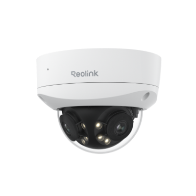
Reolink Duo 3V PoE
The Reolink Duo 3V PoE is a heavy-duty, fixed-position panoramic camera engineered for maximum visual detail and extreme physical durability in high-risk areas.
-
16MP UHD Dual-Lens Panorama: Utilizing dual 4K image sensors and an advanced quad-core SoC, this camera seamlessly stitches two lenses into an ultra-wide 16MP panoramic view. It delivers enough clarity to read license plates of parked cars up to 16 meters away, effectively replacing two standalone cameras with a single PoE drop.
-
IK10 Vandal-Proof & IP67 Rated: Enclosed in a rugged, explosion-proof dome housing, this camera carries a verified IK10 vandal-proof rating. It is explicitly built to withstand heavy physical impacts, tampering, or blunt force trauma from objects like bats or clubs while maintaining its airtight IP67 weatherproof seal.
-
Intelligent Motion Track: Beyond standard smart detection, the built-in AI processes movement paths and creates a single-image summary showing the entire motion trajectory of a target over a 15-second window, saving you from scrolling through lengthy video timelines.
-
Active Deterrence & Color Night Vision: Outfitted with a large F1.6 aperture and 6 powerful spotlights, it captures high-detail color video all night long. Upon identifying intruders, it deploys a double-defense mechanism by flashing the spotlights and triggering a high-decibel integrated siren.
16MP Dual-Lens IK10 Vandal-Proof PoE Camera
16MP Ultra HD, 180° Panorama, Motion Track, IK10 Vandal-Proof, color night vision.
FAQs
How do I terminate a Cat6 Ethernet cable?
To terminate a Cat6 Ethernet cable, start by carefully stripping off the cable jacket and exposing all the internal wires. Arrange the wires following the T568A or T568B wiring scheme, insert them into an RJ45 modular plug, and crimp the connector securely using a suitable tool. Ensure the wires are correctly aligned. Use a cable tester to verify connectivity and proper termination before deploying the cable for network connections.
What tool is typically used for terminating an Ethernet cable?
The most common tool used for the Ethernet cable termination is a crimping tool. This tool lets you attach an RJ45 modular plug to the cable by securing the wires inside the connector.
Will Cat6 Ethernet cables enhance network connectivity?
The answer is yes. Cat6 cables are engineered for higher performance and bandwidth. These cables support data rates up to 10 Gbps at a maximum distance of 55 meters. Cat6 cables have stricter specifications for reducing crosstalk and interference enhancing network connectivity within your home or a small business.
Conclusion
Terminating an Ethernet cable is essential for establishing robust and efficient networks. Compared to Cat5e termination, terminating Cat6 cables requires higher precision regarding wiring configuration and installation. After reading this article, do you understand the basic steps to terminate Ethernet cables? Please share your thoughts with us, and let's discuss them in the comment section below!
Search
Subscribe for the Latest Updates
Security insights & offers right into your inbox