
PoE Pinout: RJ45 Wiring, Modes, and Pin Configuration
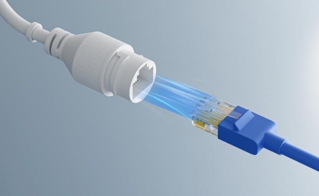
Understanding Power over Ethernet (PoE) pinout configurations is vital for properly wiring PoE devices on your network.
In this article, we will provide an in-depth look at PoE pinouts, covering RJ45 PoE pinout standards, best practices for wiring Ethernet pinouts for PoE, and the benefits of proper PoE camera pinouts. Proper PoE pinouts support easy device installations, reduce cable clutter, and enable remote power supply. Let’s take a complete look.
What Is a PoE Pinout?
PoE pinout refers to the specific pin assignments on an RJ45 Ethernet cable used to deliver both power and data to PoE-capable devices. The ethernet PoE pinout allows Ethernet cables to carry electrical power along with data on the same cable to devices like VoIP phones, security cameras, access points, and more. This removes the need for these devices to have their own dedicated power supplies.
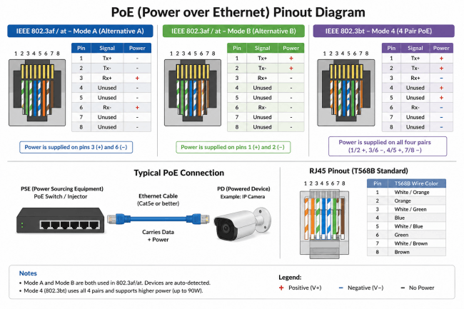
PoE Pinout Diagram
RJ45 PoE Pinout Configuration
An RJ45 connector has 8 pins arranged into four twisted pairs. In a PoE connection, these pins carry Ethernet data, electrical power, or both, depending on the PoE standard and power delivery mode.
For 2-pair PoE, there are two common RJ45 PoE pinout configurations:
- Mode A / Alternative A: Power is delivered over pins 1, 2, 3, and 6
- Mode B / Alternative B: Power is delivered over pins 4, 5, 7, and 8
Higher-power IEEE 802.3bt PoE can use all four twisted pairs for power delivery.
Mode A PoE Pinout
Mode A PoE uses pins 1, 2, 3, and 6 for both Ethernet data and power. Power is injected through the center taps of the Ethernet transformers, allowing data and electrical current to travel over the same wire pairs.
A typical Mode A PoE pinout is:
- Pins 1–2: Data pair + PoE power
- Pins 3–6: Data pair + PoE power
- Pins 4–5: Other Ethernet pair
- Pins 7–8: Other Ethernet pair
Mode A is also known as Alternative A and is commonly associated with endpoint PSE devices such as PoE network switches.
Mode B PoE Pinout
Mode B PoE delivers power over pins 4, 5, 7, and 8. In 10/100 Mbps Ethernet, these pairs were traditionally called spare pairs because data traffic primarily used pins 1, 2, 3, and 6.
A typical Mode B PoE pinout is:
- Pins 1–2: Ethernet data
- Pins 3–6: Ethernet data
- Pins 4–5: PoE power
- Pins 7–8: PoE power
Mode B is also known as Alternative B. It is commonly associated with midspan PoE injectors, although standards-compliant PoE equipment can support different power delivery arrangements.
For Gigabit Ethernet, all four twisted pairs carry data, so pins 4, 5, 7, and 8 should not simply be described as “unused.”
4-Pair PoE Pinout
4-pair PoE uses all eight RJ45 pins for power delivery. This approach is used by IEEE 802.3bt to provide more power than earlier 2-pair PoE standards.
The 4-pair PoE pinout combines both pair sets:
- Pins 1–2: Data + power
- Pins 3–6: Data + power
- Pins 4–5: Data + power
- Pins 7–8: Data + power
By supplying power over all four twisted pairs, 802.3bt can support devices with higher power requirements, such as advanced PTZ cameras, wireless access points, and other high-power network equipment.
How Does PoE Ethernet Wiring Work?
Modern PoE uses active negotiation: the power source (PSE) sends a low-voltage pulse to verify the powered device (PD) requires power before sending full voltage (typically 44V–57V DC).
-
802.3af (PoE): Up to 15.4W per port (12.95W delivered to device).
-
802.3at (PoE+): Up to 30W per port (25.5W delivered to device).
-
802.3bt (PoE++ / 4PPoE): Up to 60W to 90W per port using all 4 pairs.
Power over Ethernet (PoE) wiring delivers both electrical power and data over a single standard Ethernet cable (such as Cat5e, Cat6, or Cat6a). This eliminates the need for a separate AC power outlet near networked devices like IP cameras, Wi-Fi access points, and VoIP phones.
PoE Pinout for Security Cameras
Choosing the appropriate Ethernet cable builds reliability into your PoE infrastructure. Here are the top cable recommendations for PoE cable pinout wiring:
Category 5e and Above
Cat5e cables comfortably handle PoE for today's networks. The solid core maintains performance over distance while still remaining cost-effective at scale. Using Category 6 or 6a for future-proofing PoE installs provides headroom for higher wattages and bandwidth.
Shielded vs Unshielded
Shielded cables better reject electromagnetic interference (EMI) that can disrupt transmissions. This makes them preferable for industrial environments. However, unshielded cables work for most typical PoE security cameras and WiFi access point connections.
Outdoor-Rated Cables
Running PoE wiring outdoors requires using cables designed to withstand weather elements, temperature extremes, and other environmental rigors over time. Choose exterior-grade cables with UL verification for any outdoor PoE extensions.
Maximum Length
Allowable Ethernet cable distances decrease as delivered PoE wattages rise. Always check cable run length restrictions based on your PoE switch and connected device standards. Exceeding stipulated lengths bottlenecks electrical current, reducing PoE wattages.
Carefully wiring Ethernet infrastructure for PoE enables devices like VoIP phones, PoE video cameras, access controls, badge readers, and thin clients to be deployed easily without local power. Paying attention to pinouts, modes, switch ports, runs, and proper cables keeps these PoE-powered systems humming.
PoE Pinout Wiring Best Practices
Installing Ethernet infrastructure for PoE requires care to avoid connectivity or power issues. Follow these best practices when wiring ethernet pinout PoE:
1. Verify PoE Standard Compatibility
Ensure the PoE switch, Ethernet cabling, and powered device all support the same PoE standard. Mismatched ethernet PoE pinout standards can lead to connectivity loss or even equipment damage. Common PoE standards include 802.3af, 802.3at, and 802.3bt.
Tech Note for High-Bandwidth Setups: While standard 802.3af is enough for basic hardware, next-generation flagships like the Reolink OMVI 3i PoE demand the advanced capacity of the IEEE 802.3at (PoE+) standard. The OMVI 3i PoE integrates an innovative 18MP triple-lens configuration (combining a 10MP panoramic display with an 8MP 4K Pan-Tilt camera). To support this heavy data load and power the built-in spotlights seamlessly through a single rj45 pinout, matching your wiring to the correct PoE+ switch standard is critical to prevent mid-stream packet loss or power drops.

All-in-one Triple-Lens 180° Panoramic Pan-Tilt Security Camera
10MP Dual-Lens 180° View, 4K 360° Full Coverage, SyncTrack with auto framing & auto tracking, Local Storage (No Monthly Fees), Local AI Video Search.
2. Choose the Correct Mode
Confirm whether the PoE switch and target device use Mode A or Mode B RJ45 PoE pinouts. Using the wrong mode prevents the powered device from functioning properly. Most PoE equipment today works in Mode A.
3. Connect to PoE Switch Ports Properly
Plug equipment only into PoE-enabled switch ports. Connecting to non-PoE ports not only stops power transmission but also risks damaging Ethernet switch components. Disable unused PoE ports.
4. Watch Cable Lengths
Adhere to maximum cable run lengths based on PoE standards to avoid power transmission loss. For example, 802.3af supports 100 meters, 802.3at up to 150 meters, and 802.3bt allows 600 meters.
5. Use Proper Cabling
Choose solid core Category 5e or higher cabling for reliability. Stranded PoE ethernet pinout cables often do not make consistent contact with RJ45 connectors, leading to physical issues.
Paying attention to these key steps when wiring PoE pinouts prevents networking problems, improves PoE device uptime, and avoids damage. It also makes installing additional PoE endpoints easier later on.
Benefits of Proper PoE Camera Pinout
Security cameras represent one of the most popular uses for PoE on Ethernet networks. Running cameras over PoE with correct RJ45 pinouts provides tremendous installation, operation, and maintenance advantages compared to traditional analog cameras.
Easy Cable Management
A single Ethernet cable delivers both data and power from the NVR to each PoE camera pinout. This eliminates the hassle of pulling and connecting power cables at each camera installation site. Network video recorders (NVRs) also take less space without bulky power supplies inside.
Reduced Cable Clutter
The single-cable PoE approach significantly cuts down cable clutter in the ceiling or conduit. Analog systems require bundles containing video coax, Siamese cables, and power wires for each camera. PoE greatly simplifies infrastructure needs.
Remote Power Supply
Cameras powered locally present issues over time as transformers degrade. Centralized power from the PoE switch via properly wired Ethernet allows easy monitoring and management of camera power status. Intelligently managed PoE power budgets prevent overloading.
FAQs
What pins are used in PoE?
PoE relies on pins 1, 2, 3, and 6 for power transmission in Mode A pinouts. For Mode B, pins 4, 5, 7, and 8 handle power delivery instead. Data transmission occurs over the other spare pins.
Does PoE need all 8 wires?
No, only 4 of the 8 RJ45 wires carry electrical current. However, using all 8 wires allows simultaneous data communication. Two-pairs handling power enables reliable delivery over longer distances.
Is PoE+ the same as 802.3at?
Yes, PoE+ represents the IEEE naming for products adhering to the 802.3at standard. Similarly, PoE++ corresponds to equipment meeting the 802.3bt specification defined by the IEEE.
Conclusion
Getting PoE pinouts correctly wired ensures seamless network connectivity and power for devices like security cameras, wireless access points, and VoIP phone systems. Paying attention to PoE modes, switch ports, and Ethernet cable specs when planning and installing PoE allows reliable powering of equipment remotely over a single cable, reducing clutter and installation headaches.
Do you understand PoE pinout now? Share your thoughts with us in the comment section below so that we can discuss together!
Search
Subscribe for the Latest Updates
Security insights & offers right into your inbox